 |
|||||||||||||||||||||||||||||||||||||
|
|
|
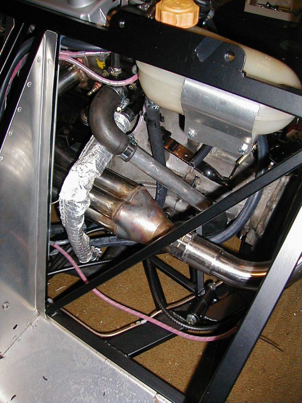
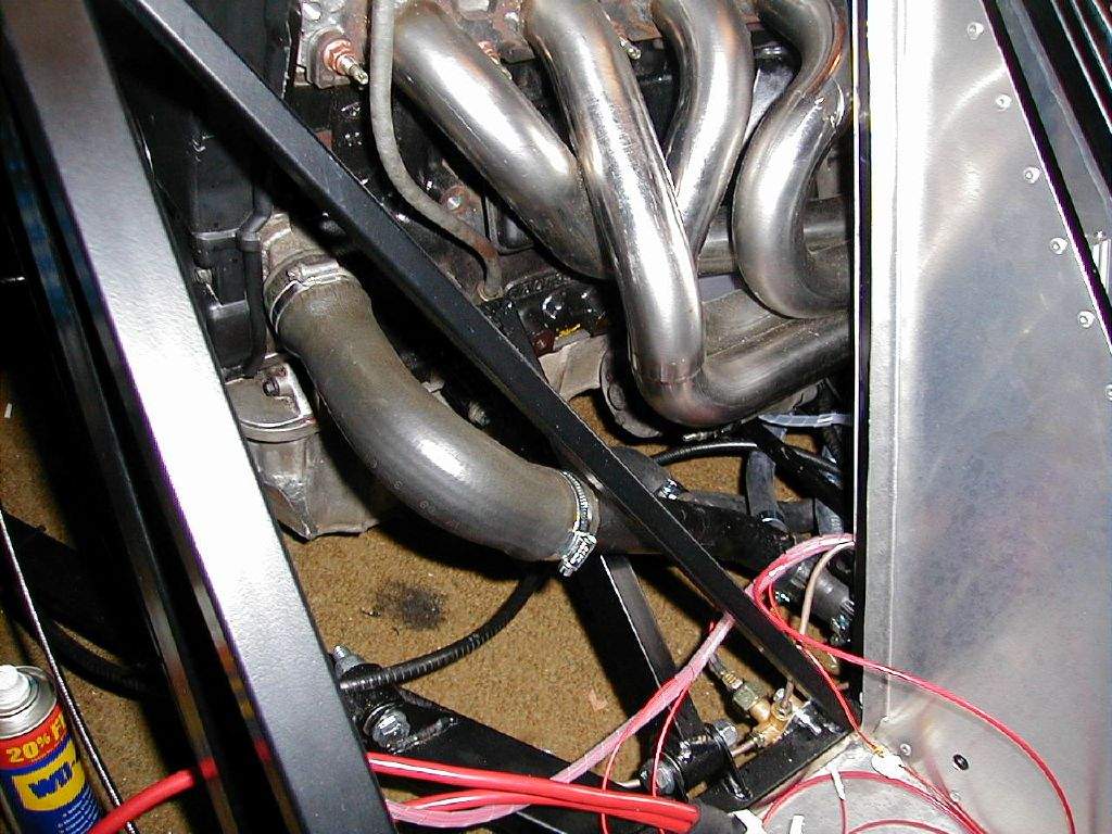
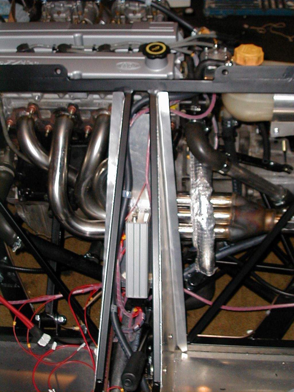
1st April: 1h30m: Stripped out a couple of lengths of cable from the original engine loom with connector still attached, to reuse on my crank position sensor. This will be wired back to the ECU. Jeremy Phillips had mentioned he fitted a small heat shield, as the sensor is within a couple of inches of the exhaust primary tubes, and wiring brings things even closer together. I will have a go at making something out of a scrap of aluminium plate, but it will be 'fun' to fit as things are a little crammed in. If you're building a zetec Mojo, do this before fitting the exhaust…. You live and learn I suppose! Also fiddled around some more with the rad hoses, deciding how to route things. While I'm on this subject, I'll talk a little about the way I intend plumbing things up. This is a bit techie, so move on if it's boring you…!The large 32mm outlet on the front of the thermostat housing will go straight to the radiator top via the tunnel. Jeremy Phillips at Sylva seems to plumb the header tank into this section at the low point in the system just in front of the gearbox, although the original Ford setup has the header tank plumbed into the low point of the bottom hose. Maybe it doesn't matter seeing as both the top and bottom hose drop to the same level in the Mojo, along the entire length of the tunnel, and it is more convenient to tap into the top hose as it is sensible to mount the header tank on the left of the engine bay. I will take the approach that either top or bottom hose will do the trick (whichever is more convenient), so long as the header is plumbed in at the low point. Moving on, the smaller outlet on the front of the stat housing just below the main top hose outlet is the bypass. Steve Knee informs me that Jeremy Phillips suggests simply blocking this off, but I am not too sure about doing this. The bypass should connect the outlet on the stat housing directly to the bottom hose, 'bypassing' the radiator, and is there to allow a small amount of flow around the engine before the stat opens. With the bypass removed, there is nowhere for the water to flow, but the water pump will still be trying to pump water around the system. The problems I see with this are: - The water pump will generate higher than normal pressures in the system. - The lack of flow will mean hot spots can develop in the block. - The stat will only open once the water in the stat reaches the stat opening temp. The lack of flow means that the water in the stat will only be heated up by conduction / convection of the heat, rather than by the physical movement of hot water. The water in the block may well be significantly hotter than the water in the stat when the stat opens… - The temps senders mounted to the stat will not give a good indication of the water temp until the stat opens. So, as you may have guessed, I will be plumbing in the bypass! I think in my case it is a little less important, as I'm plumbing in a heater, which should also allow some flow through the heater matrix before the stat opens. However, to be on the safe side, I'll still plumb the bypass in… Let's hope it works! Continuing, the tiny connector on top of the stat housing should connect to the top connector on the header tank- this is the air bleed. The remaining connection on the rear of the stat housing is the feed to the heater matrix. I will need about 3 metres of heater hose to reach the matrix at the front of the Mojo. The outlet from the heater matrix is normally plumbed in to the bottom hose just before the water pump. However, since my heater is at the front of the car and the bottom hose runs from the front to the back, I have teed in the heater matrix outlet to the bottom hose at the front of the car, using a bend with moulded in off-take (another scrap yard find!). 2nd April: 1h30m: Continued work on the cooling system, modifying the plastic T-piece to suit. My header tank will be plumbed into the bottom hose along with the bypass (the plastic section actually has two Tees off the main pipe). 3rd April: 4h30m: Bought some 32mm aluminium tube from my local(ish) Metal Supermarkets to enable me to continue with the plumbing. Realised that one of the pipes running through the tunnel would have some clearance problems with the gear linkage. I had positioned both tubes to the right of the tunnel, but ideally they should be on opposite sides. Thankfully, I was able to undo the securing clips (glad I used rivnut fixings!), flip them round and re-secure using the same rivnuts. I then connected the main outlet on the stat to one of the tunnel pipes, followed by a long length of heater hose from the matrix in the front to the outlet on the rear of the stat. At this point the area of the engine bay just to the rear of the tunnel began to look like a spaghetti of handbrake & clutch cables, gear linkages and hoses! I did my best to make it look neat and tidy, but with little success...
4th April: 2h30m: Bahrain GP day, so not too much work today! Made up a bracket to mount the Sierra header tank to the top bulkhead chassis rail. The air bleed lines up perfectly with the outlet on the stat! The header tank will require an extra mount at the rear to secure properly. 5th April: 1h45m: Heard from Steve Knee, who had decided to try using the bypass in his cooling system plumbing, after some problems with temp sensors giving low readings until the stat opened. Thankfully, adding the bypass had improved matters, so I will be following suit. Thanks to Steve for trying it out! Made up the rear bracket for the header tank and riveted to the upper side chassis rail.
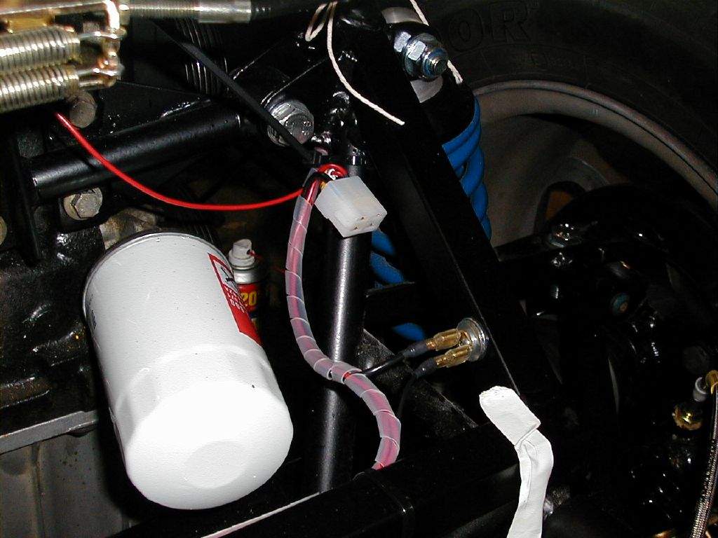
Spent some time trying to work out how to mount the fuel pressure regulator. Jeremy Phillips and others have mounted this at the front of the Mojo, but ideally it should be as close to the carbs as possible, so I intend mounting it at the rear. My ideal solution was to fit it between the header tank and the engine, but this area is a bit cramped, the air bleed from the stat to the tank being a particular problem. No solution came to mind tonight, so I will sleep on it... 6th April: 1h30m: Managed to package the pressure regulator in the location I originally intended, between the header tank and the engine. The bracket (which came with the regulator) is rivnutted to the top bulkhead chassis rail, and passes beneath the air bleed hose. I just need to source an additional 90 degree fuel union to finish.
Connected up the fuel hose between the carbs. 7th April: 1h15m: Connected the header tank to the bottom hose. The 15.8mm heater hose I'm using was an extremely tight fit- dunking the ends in hot water helps to soften the rubber! Tried to attach the bypass pipe to the thermostat outlet, but this really didn't want to fit, and my hands were aching from the header hose... A job for another day! 8th-17th April: No work on the Mojo as we were away for a week in Glencoe. We walked on all but one day, and managed a few Munros towards the end of the week, as the weather improved- we even saw the summit of Ben Nevis with NO cloud cover, a rare site indeed! 18th April: 2h15m: Had a second attempt at fitting the bypass hose to the thermostat, the holiday obvious re-energised me as it went on no problem! As this hose will pass a few inches over the exhaust, and then down the rear bulkhead, I've taken the precaution of sleeving it with a handy piece of heat reflective material off a scrap car. I've joined this flexi hose to a more rigid one with a couple of formed bends, which conveniently links it up to the T connection on the piece of pipe running up towards the water pump inlet. At this point, the only missing piece in the cooling system is a 90 degree bend to connect onto the water pump housing. A trip to the scrapyard is called for at some point...
19th April: 1h30m: Picked up a package from the Post Office- the modified gearbox link piece from Jeremy Phillips at Sylva. First job was therefore to fit the link rod from the gear lever to the gearbox. My different Focus mechanism means that I don't need to reverse the direction of this rod with a rotating link- I can connect the rod straight through. I therefore joined the 2 piece rod with a short section of threaded rod, instead of using 2 rod ends and the rotating link. The next problem I came across was that the different link setup resulted in a slightly different angle across the car, which meant the rod caught the lower edge of the gearbox casing. I decided that there should be no problem with a slight kink in the link rod, so a bit of rod bending was carried out! The final problem, as I had expected, was with clearance through the spaghetti of pipes and cables at the rear of the tunnel. It's better than I expected, but I'll have to do a bit of fiddling to get one handbrake cable and the clutch cable out of the way, but the important thing is the link works- unfortunately, I don't have the cable part of the gear linkage yet, so I can now only shift from 3rd to 4th and back again, but the lever has a nice short throw, so things are looking promising!
20th April: 1h15m: Did a bit of work on wiring the final few connections into the ECU multiplug. Once finished, I thought I would check the power supply to the ECU was working OK. The Emerald ECU has an LED on the outside of the casing which lights up once power is present, so I would know if things were looking OK. Since the dash isn't wired up properly at this stage, I had to do a bit of temporary wiring bodging to get things connected. On turning on the ignition, the LED lit up and 'bzzzzzzzzzzzzzzzzz' what the heck is that noise? Ignition off quickly before I realised it was the ECU running the fuel pump, phew! 21st April: 2h00m: A bit more wiring- crimped on a connector for the oil pressure sender & fitted the left and right hand side 4 pin multiplugs that will serve the rear lights. These both required a local earth (I've got a single main earthing point at the front of the car, but I decided not to run earth runs all the way to the rear), so I fitted these to the rear chassis rail. For these earthing points, I removed the powder coat from an approx 20mm diameter, fitted a rivnut into the centre of this region, then fitted a washer such that the washer sits against the chassis rail, and not the rivnut (the hole in the washer needs to be bigger than the outer diameter of the rivnut).. The main earthing path is through the washer (earthing through just the rivnut seemed a bit dodgy!). Whilst I was at it, I also fitted the earthing strap to the engine, using the same method, only with a bigger rivnut!
22nd April: 1h15m: Removed the dashboard, which means taking out the vents & vent distribution box, in preparation for wiring the dash in properly. 23rd April: 4h15m: Went to the scrapyard in search of an alternator pulley to suit the Zetec multi-groove belt (the alt. has a V-belt at the moment), an alternator tensioner arm (to use in conjunction with a custom made bracket) and the final piece of radiator hose to complete the cooling system. Frustratingly, I came away with 2 bits of hose that I thought would be too small- nothing else. Tried the hoses when I arrived home, and as I feared, neither appeared to want to fit. One was distinctly closer to going on though, so I fitted it over a slightly smaller bit of tube in the hope that the rubber would stretch enough to allow me to fit it onto the water pump tomorrow... Frustrated with the cooling system, I decided to make a start on wiring up the back of the dashboard. I need to do this to test the wiring properly in advance of getting the engine started. Most of the crimp connectors for the live feeds were already in the dash loom, but these needed connecting up to switches, warning lights etc, and then all the earth runs making up. Once this was done, I had to figure out exactly how to get my main battery feeds behind the dash to the isolator switch. I did this by getting the dash roughly in place and then seeing where I had any space. Trouble was, the rear of the dash was now completely filled with cables, so this was a challenge! With the dash finally in place and wired up, I refitted the heater vents.
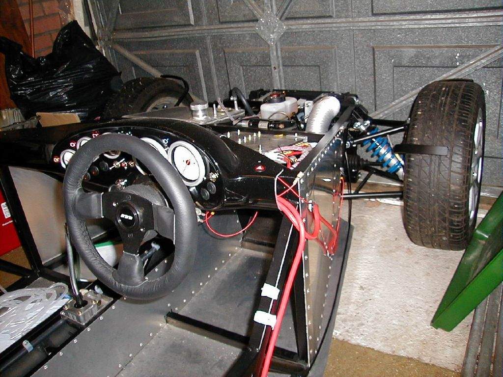
24th April: Bought some bulbs for my indicators and tail/stop lights, in preparation for testing the wiring. Had some friends round for the afternoon, so didn't make any more progress... but it was nice sitting out in the garden in the warm sunshine! 25th April: 1h15m: Everything was now ready to enable me to check the wiring- GULP! I started with the wiring circuits. I temporarily fitted some terminals to 2 of my indicator units, which I planned to use to test all of my lights, one light at the front, one at the rear. I removed all the fuses from the fusebox, with the exception of the sidelight circuit- I would test this first. Hmmm. Nothing doing when I flip the switch, so out comes the multimeter. Hmm, circuit seems live at the switch... live at the fuse... live at the connector to the lamp... aha, it might be useful to fit a bulb to my test lamp! With that problem sorted, sidelights, gauge backlights, headlights, main beam, tail lights, brake lights, fog light feed were all tested and worked fine- the only error on my part was I had forgotten to wire in an earth to the main beam warning lamp- I realised I had missed this yesterday as, from behind the dash, the warning lamp is hidden behind the bulk of the speedo and tacho. Easy to fix when the dash comes off for painting in a few weeks. Next was the indicators/hazards, and once again, nothing happened. This was not a total surprise, however, as Steve Knee had let me know the previous week that when testing his wiring, he found that the flasher relay labels on my wiring diagram were incorrect- 49 and 49a were the wrong way round for his installation. I hadn't changed them before testing just in case my relay was labelled differently to Steve's, but the non-working indicators pointed straight towards this issue. I swapped the terminals round, with the use of a mirror and my 2 pairs of hands, and hey presto, things worked- indicators and hazards! Moving on- Gauges seem OK (can't be tested properly yet, with no engine running, but the needles move a little when ignition is switched on, although fuel gauge moves with a bit of 'manual intervention' on the fuel tank float arm!), heater blower OK, screen wash motor OK, wiper feeds OK (tested with the multimeter as wiper not connected yet), handbrake warning/fluid resevoir warning lamp OK, fog light warning lamp OK... I think that's it for now! Piccy to prove it works:
While testing the wiring, I realised that I hadn't run the cable for the rear number plate light. This runs off the right rear sidelight feed, so was easy to add in, connected into the multiplug. Tried the 'stretched' radiator hose onto the water pump housing, and yippee, it now fits!
Mounted the ECU into the tunnel- hopefully this won't have to come out again, as it's a real fiddle to fit- that is my fault for deciding to fit it into such a confined space though!
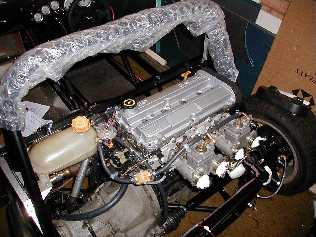
26th April: 2h45m: A nice warm day again, so decided to have a go at spraying the cam cover: Removed the cam cover, removed the baffle plate from inside, and then thoroughly cleaned and degreased using GUNK, then rinsed in water. Masked off the breather hose, filler hole and a few other small areas, and then got shaking the can of spray paint. I had previously bought this- it is specifically for engines, so has a high temp resistance, does not require a primer, and allegedly dries quickly- sounds good to me! Applied 3 coats, with 20 mins between coats as recommended on the can. I'm really pleased with the result, it will smarten up the engine bay massively!
With the chance of a few visits from other Mojo builders this coming weekend (the Stoneleigh show is only about 3 miles up the road for me), the garage was treated to a clear up- it had become a complete mess once again! 27th April: 1h15m: Cleaned up the top face of the cylinder head prior to fitting the cam cover. Fitted the new rubber gasket and bolted the cam cover in place, followed by the spark plug leads and the cam belt top cover. Engine is looking really smart now!
Total time spent during April: 32h15m
|
|||||||||||||||||||||||||||||||||||
|
|
|||||||||||||||||||||||||||||||||||||