 |
||||||||||||||||||||||||||||||||||||||||||||||||||
|
|
|
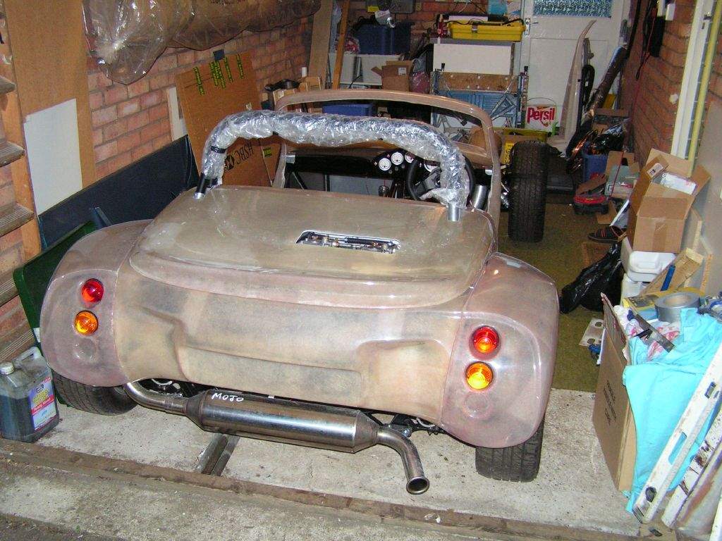
1st June: 1h45m: Carefully started chopping two slots in the engine cover to clear the rear stays of the roll bar. This was another case of measuring 10 times, marking out on the fibreglass, checking the measurements once more, and then letting the dremel do its stuff! A bit of fine tuning was required, as usual, but eventually it sat in place, albeit an inch or so too high due to the carb clearance problem. I knew in advance that I was likely to have this problem- Sylva can now provide a bond-in bulge/scoop (see the Sylva website) for Zetec engined cars, but it's a bit OTT for my liking. Ideally I wanted no bulge or scoop, but without a custom manifold to get the carbs to sit lower, a bulge/scoop was going to be required. I decided that it was best to work out how much material needed cutting away before trying to source a scoop, so I started with some tentative small holes drilled into the engine cover to enable me to see where the carbs were sat, before opening the holes up a little at a time, checking how the bonnet improved in fit as time went on. 2nd June: 2h00m: Took the day off work today, and went on a shopping spree (for the car, of course!). Bought vinyl and carpet for trimming, mesh for the grilles, glass fibre repair kit, liquid rubber for the underside of the wheel arches (from B&Q in the roofing section), bonnet locating pins from W*stf**ld (£3.25 each for a bit of turned aluminium!). Had intended buying my harnesses from W*stf**ld too, but infortunately they have recently customised the Willans harnesses to read 'W*stf**ld'.... I'm not having that in my Mojo! I also stopped by Aldon Automotive to have a nosey at air filters. I realised that at the moment I am cutting the engine cover hole to clear the carbs with no filters fitted. A set of K&N type filters would require the bulge to be much deeper from front to back, so I looked at the sock type filters to see if I thought they would fit under the original engine cover moulding. Unfortunately Aldon didn't have any 50mm deep filters, which I know are available, so I didn't buy anything... But, the socks were looking more promising, so I think I will order some. On returning home, I increased the size of the hole in the engine cover, such that it now almost fits correctly. A small amount of trimming is required where the shape of the flange is not quite right on the tub, then it will fit perfectly. The hole is now about 100mm from front to back, and about 300mm wide.
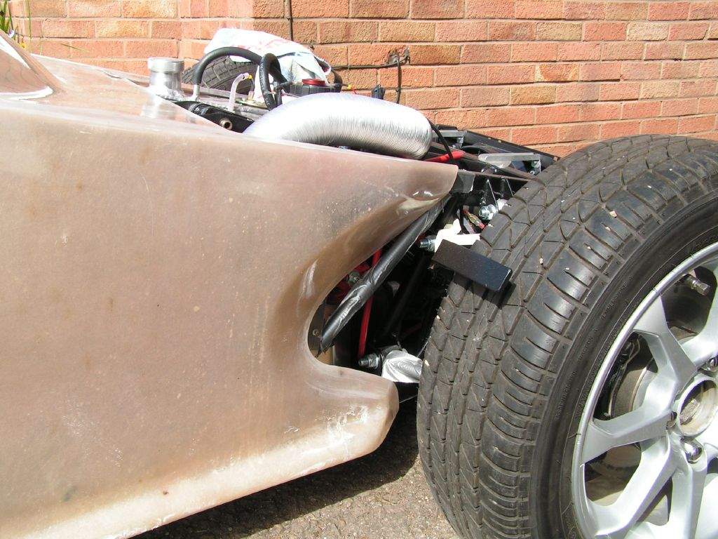
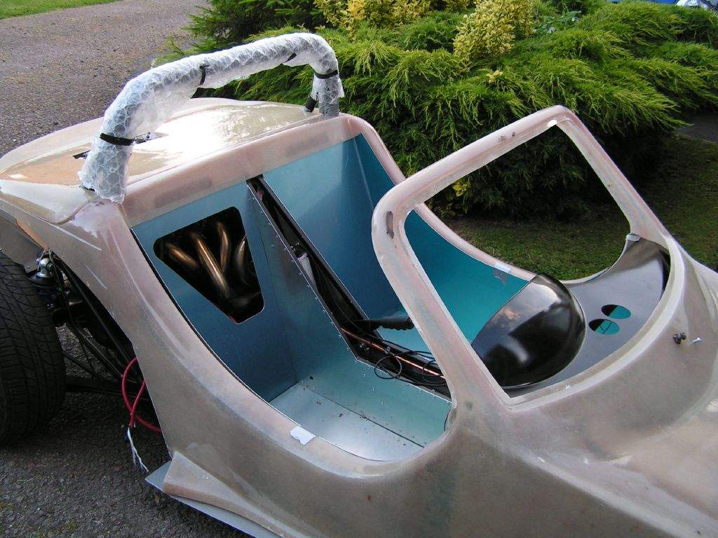
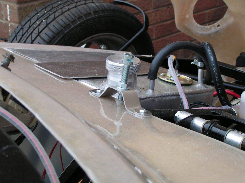
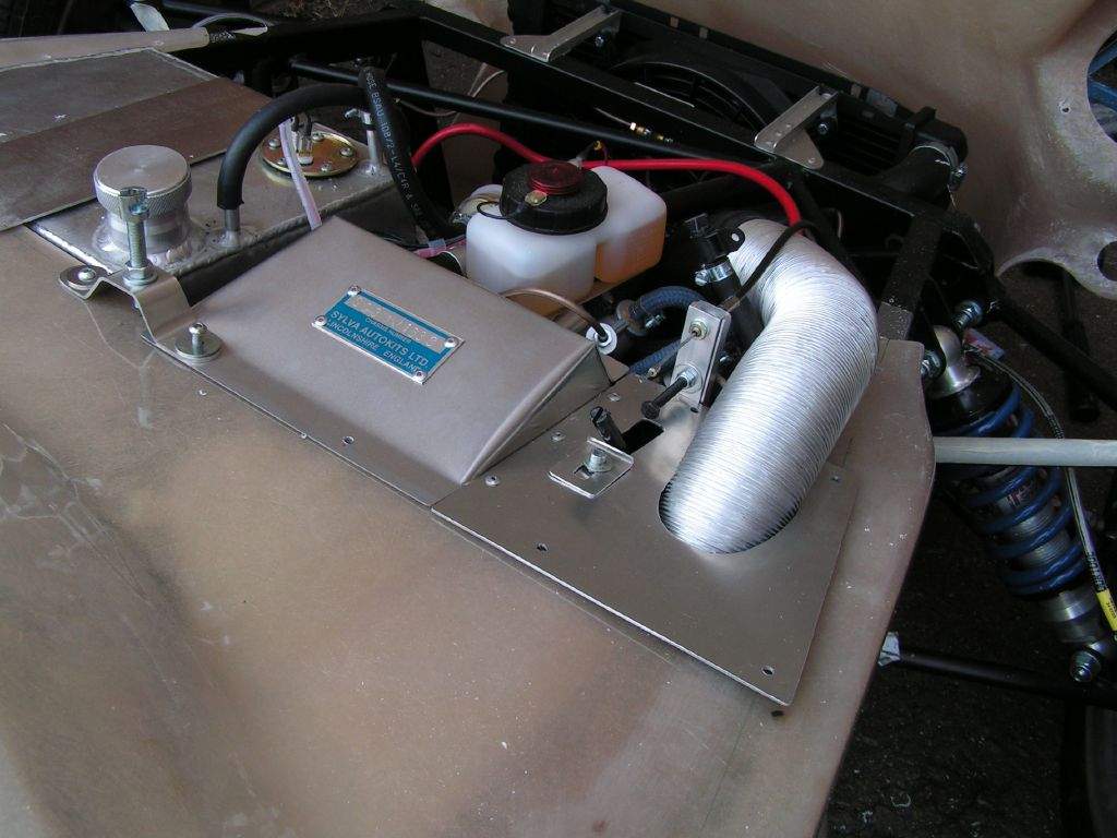
Did a bit of searching for suitable bonnet bulge or scoop on the web, bulges don't really seem to exist, but I've found a fairly simple, small scoop designed for a mini (original version) which I think may look OK, and it is about the right size. 3rd June: 2h00m: Ordered some Pipercross dual trumpet socks, 50mm deep, from Trackstore, who were the cheapest supplier I could find. Made up a bracket for the rear fog light. After much deliberation over whether to flush mount a lamp above the number plate (Steve Knee has used a Peugeot 206 item), I have decided to use a cheap and cheerful unit mounted below the number plate, above the exhaust. I had to mount it slightly oddly to get it to the 250mm above ground required for SVA, so the mounting lug is on the bottom with a small bracket that is bolted to the lower edge of the tub. After SVA, I have my eye on one of these from Maplin, mounted in a similar location but recessed more under the body. Various chaps from blatchat have used these as either high level brake lights or fog lights, they are allegedly the same product as can be bought from Merlin and Demon Tweeks, with the exception that they're £9.99+VAT at Maplin, and over £40 from the other suppliers... Interestingly, in the Merlin brochure it is claimed to be an MSA approved high visibility rain light for single seater racing, so it should do the job! Not sure what the SVA man would think, so I'll change it afterwards! 4th June: 3h30m: Air filters arrived, so tried them in place to check the engine cover would clear them- other wise I'm going to have to increase the size of the cut out. I think I'm in luck- the filters just touch the engine cover, but aren't really being squashed, so I think that will be fine. I will probably stick something to the underside of the cover, just to stop any roughness in the fibreglass from damaging the filter foam. With that resolved, I ordered the mini scoop from ccmotorsport. I then removed all the bodywork for a fibreglass-cutting fest! Here are the filters with the body removed:
Removed yet more material from the front side edges of the tub- this will make fitting and removal easier, plus it solves a bit of a clearance problem on the drivers side with the very end of the footwell. I had noticed that the latest Sylva demo car had been done this way, so I've tried to do the same, with a nice 'swoopy' curve.
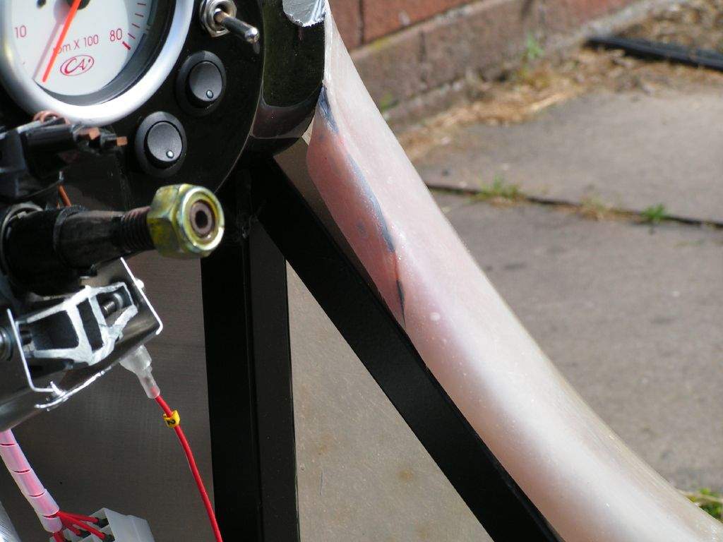
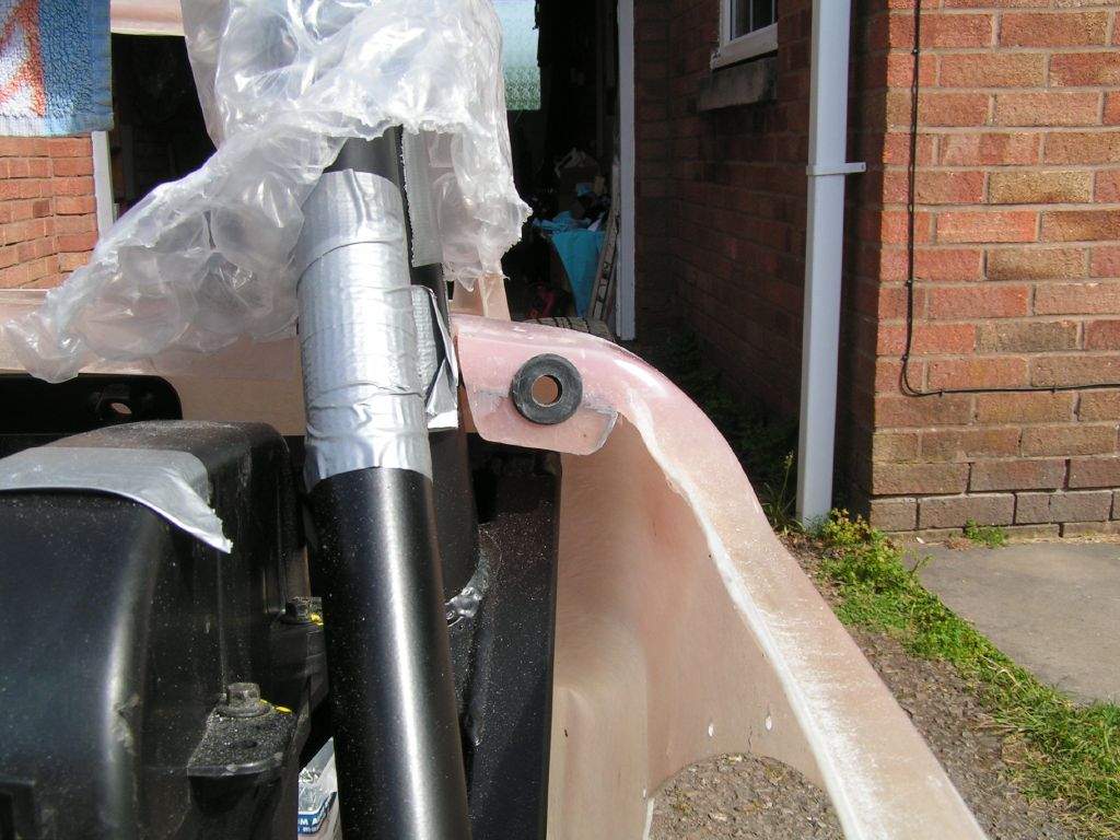
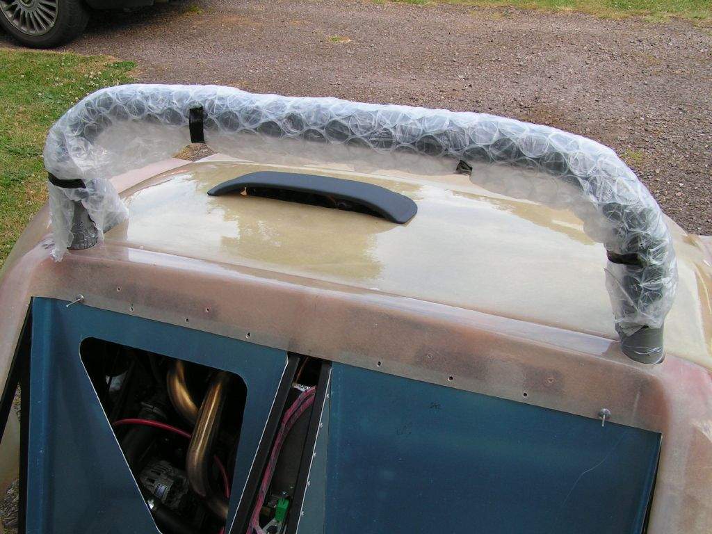
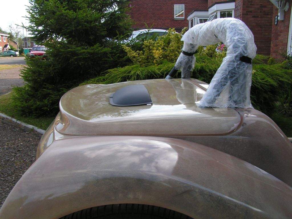
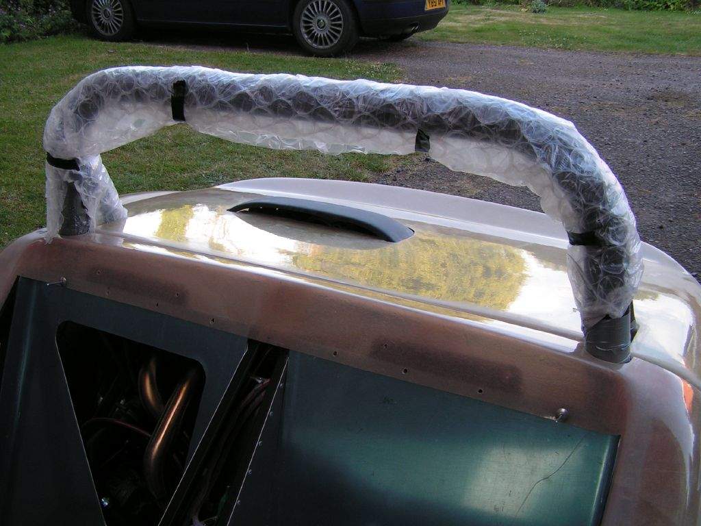
Trimmed the tub around the engine cover opening, to improve the fit of the cover. Drilled extra holes to secure the rear wings in place. 5th June: 8h15m: Wow, what an epic, my arms and legs ached at the end of today! First job- try a bit of fibreglassing for the first time in my life! I needed to extend the lower flange at the base of the windscreen, to make good were I had let rip with the dremel tool a few days ago. The aim of this was mainly cosmetic- I didn't like how the flange on the windscreen pillar continued around onto the 'sill'. I also needed to extend the flanges on the tub just to the outside of the roll bar. This was to enable me to fit the o-rings the engine cover pins obtained from Westfield will locate into. This was a bit of a messy process (I didn't take any photos until the end of the day when things were looking a bit neater!). I applied 4 layers of matting to give the four areas a reasonable amount of strength. Once the fibreglass had hardened, I used some car bumper filler, which was sanded smooth once it had gone off. Finally, I trimmed around the edges with the dremel to give a smooth finish.
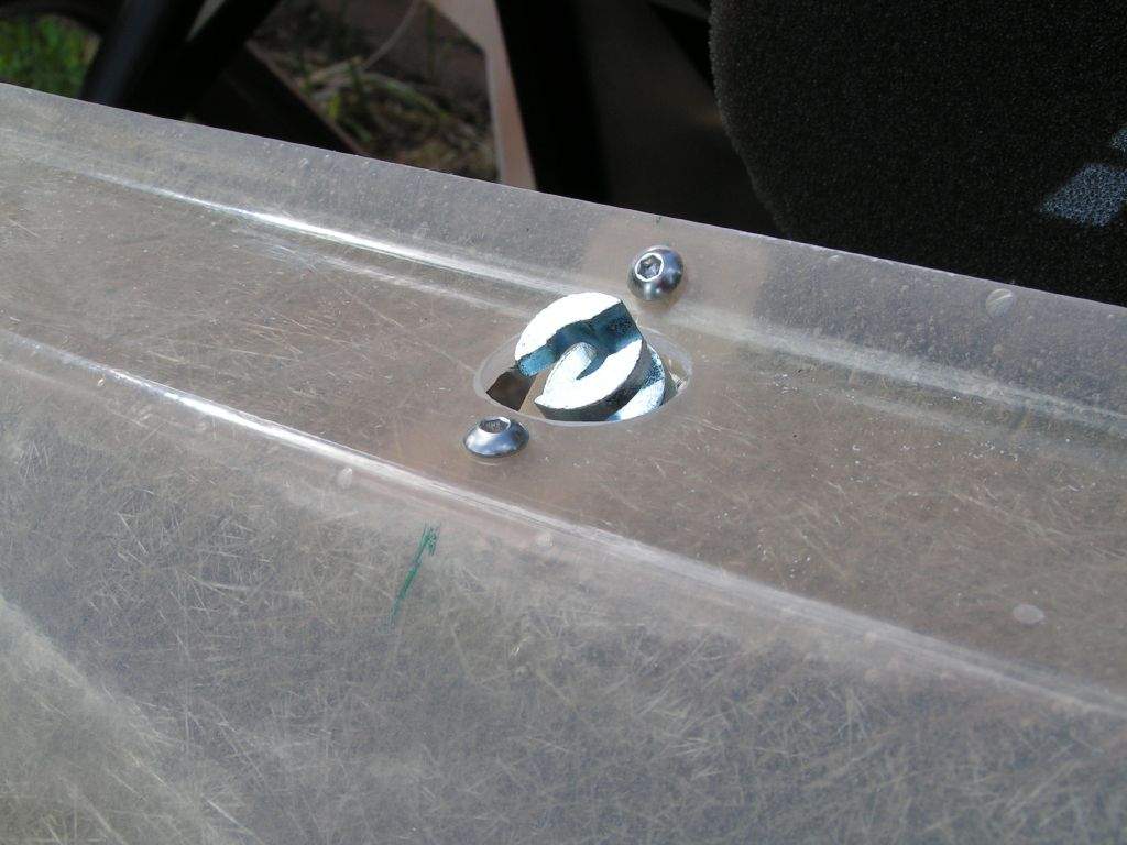
I then drilled a hole in each of the 2 flange extensions that will take the rubber grommets.
I think I'm going to have to extend the flange on the engine cover itself as well, to avoid the pins being fitted perilously close to the edge of the moulding. I'll do that when I next get the fibreglass kit out to mould in the air scoop, and fit the 'bighead' fasteners to the cycle wings... Aha, I hear you say, what on earth is a 'bighead' fastener? Well, they are simply small flat plates with holes in them, which you can order with various types of connector welded on. In my case, I'm getting hold of some which have a 12mm threaded rod sticking out from the plate. I will fibreglass the plates (4 per cycle wing) to the underside of the cycle wing, drill corresponding holes in the wing stays, and then bolt them in place from the underside- no bolts will show on the top surface of the cycle wing! As well as looking 'smooth', it reduces the problem of star cracks forming from the bolt hole, had the cycle wing been drilled. During the 'waiting times' from the process I've just described, I set to on removing the flash lines from the tub. I used coarse wet and dry paper, used wet, which meant no fibreglass dust- yippee! The main tub seemed to take forever, but the end result - a completely smooth finish - looks great! Fitted the wiper motor, as a break from all the sanding! This was easy- I had already marked out where I wanted the main spindle to come through the tub while the bonnet had been in place, so it was a simple matter of opening up the hole to 16mm, and then drilling 2 more holes for the additional mounting points. Returned to flash lines, working on the two rear wings. These have quite a few air bubbles on some of the sharper curves, so the filler will have to come out again... Easier to do with no flash lines sticking out from the moulding though! 6th June: 4h30m: Applied filler to all the blemishes I could find on the tub and rear wings. The rear wings were particularly bad around the air intakes, with air bubbles in the gel coat just under the surface. I found that some were so close to the surface that I could easily stick a finger nail in and break through in to the air bubble, so decided it was better to be safe than sorry and broke through any other areas that felt flexible, and then filled the resulting hole. Measured up for the internal side panels, the ones that butt up to the curved sides of the tub. To do this, I put the rear bulkhead panels back into place, and then did some accurate measuring... To start with, the side panels were cut out to fit against the chassis, but the top edge was left as a straight edge. This enabled the panel to be installed into position, and then the exact curve of the fibreglass marked straight on to the panel. Once again, a little bit of fine tuning was needed to get the fit to be OK, and once completed, the interior of the car started to look really quite good!
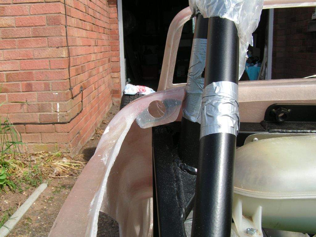
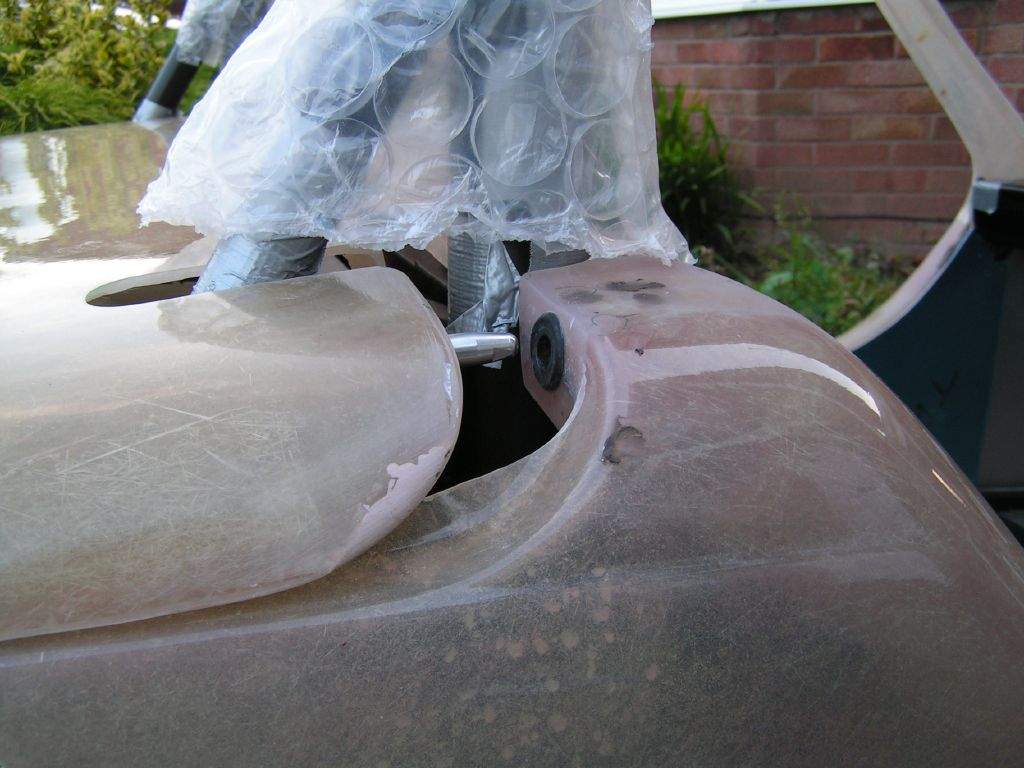
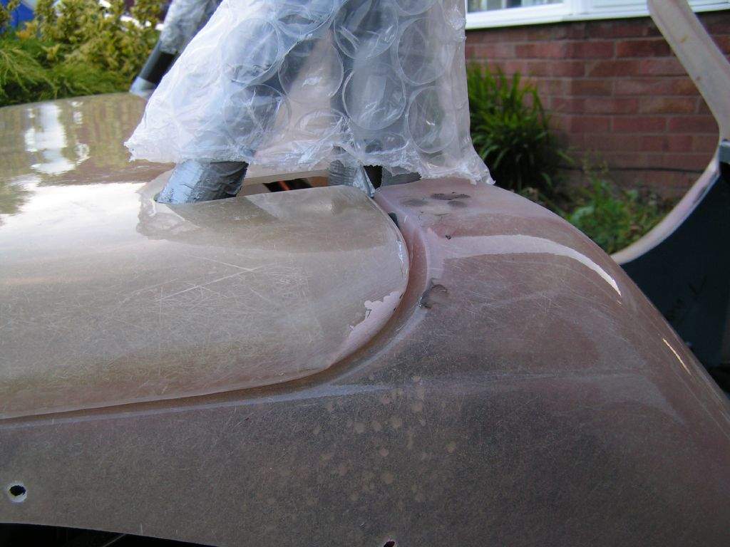
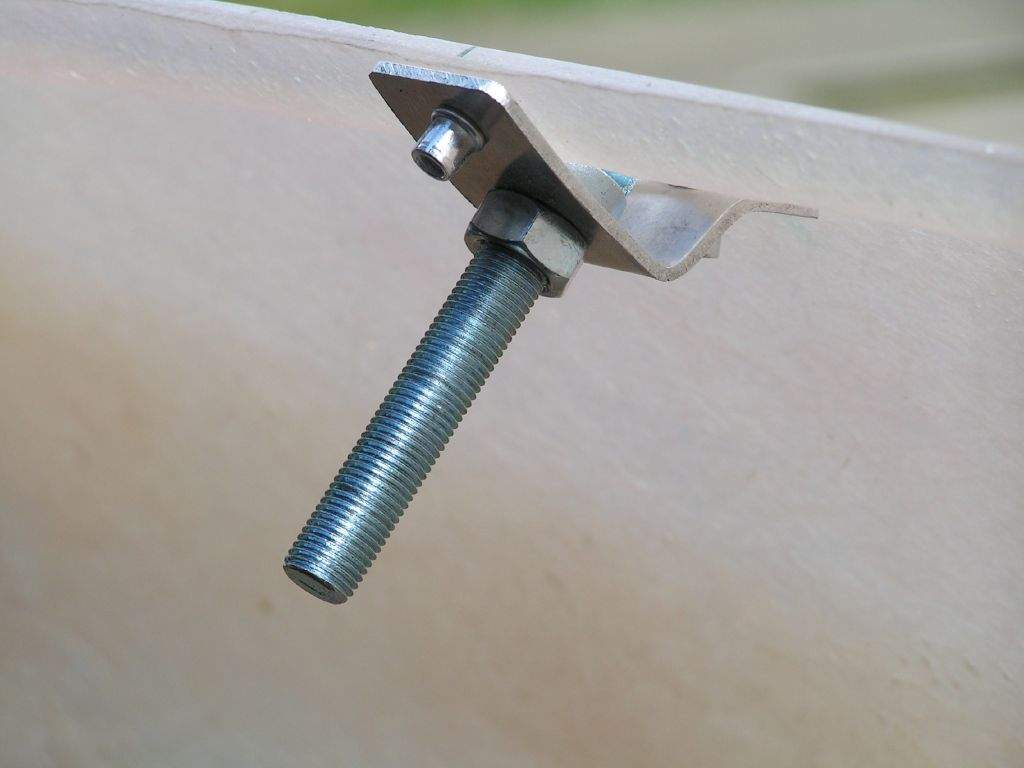
Had another look at the engine cover, and decided it was worth a try fitting the pins without extending the fibreglass lip. If it seems flimsy once I've done it, I can strengthen it at that stage. Once fitted, the pins seems plenty strong enough. Here is how they work:
7th June: No work on the car today, but I did pick up a few bits and pieces from Europa Spares as I was in the area for a seminar during the day. The booty consisted of:
8th June: 0h45m: Spent some time deciding how to mount the locking bonnet pins. These came as a pair, some people have used both on the bonnet (See Andrew Cordery's car here), some people have used one mounted centrally (See Bryan's car here). I am aiming for an uncluttered look, so will use Bryan's method. However, I don't think the large back plate / washer for the locks will be strictly necessary on fibreglass. I can understand that on a metal bonnet, the lock could cause the surrounding surface to be distorted, but the fibreglass bonnet is pretty rigid, so I'm going to try mounting it without the big washer. This will again make it look a bit neater. I initially thought that I would use a standard locking latch on the engine cover, however, it would be nicer if I could use the same key as the bonnet, so I will try and use the spare locking bonnet pin at the rear. 9th June: 1h45m: Made a bracket to support the 'pin' section of the bonnet lock. This was necessary as the pin isn't long enough to be mounted straight onto the tub or chassis (if I had mounted a pin each side, they could have been mounted straight into the tub). I made this out of some spare 3mm thick aluminium (the stuff I had bought to make the fuel tank strap) as I don't really want the bonnet flying open due to a flimsy bracket! I mounted this using rivnuts inserted into the chassis; the bracket then bolts through the tub and into the rivnut.
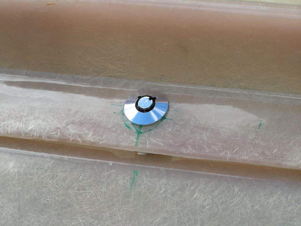
The pin could then be fitted to the bracket, and the bonnet marked and drilled out for the lock. Amazingly, the alignment was pretty much correct straight away (this would be more of a faff with 2 pins to align), a small tweak and the bonnet sits perfectly centrally, and feels very solidly mounted. No obvious problems from not using the lock surround washer either, so it looks really neat.
10th June: 1h00m: Started cutting out the engine cover for the lock unit, then went out for a bike ride for an hour or so, must make the most of the good weather! Once I got back, I spent a short while doing some more work on the lock, cutting a mount hole for the pin in the rear of the tub. 11th June: 3h30m: Continued with the engine cover lock. A bracket (oh joy!) was required to hold the pin to the tub at an angle to match the lower lip of the engine cover. I used another offcut of the 3mm aluminium sheet to do this, I' m pleased with the result:
The engine cover could then be locked in place, so another success! I'm pleased that I'll be able to use the same key for both bonnet and engine cover, cutting down on the multitude of keys that most kit cars seem to require can only be a GOOD THING! Re-sanded the rear wings where I had used filler in the air bubbles the other day. Decided that it would be best to make the pedal box cover before the body is sprayed, to save me damaging the paint during the 'trial and error' stages of the design! I have to cope with added complexity in the area as I have to also accommodate the heater duct passing through into the footwell. I have decided to split the cover into 2 main parts- a completely flat section that sits over the throttle pedal, which will have 2 holes for the upper end of the throttle pedal and for the heater duct, plus a fabricated box over the clutch and brake pedal (these protrude through the top of the pedal box, so a flat cover cannot be used). I made a start on making the flat section, integrating a bottom stop for the throttle pedal to stop putting to much tension through the cable during those occasional foot-to-the-floor moments... I used an offcut from the floor panel, wanting to use thicker material to stop the throttle bottom stop from flexing around too much. 12th June: 1h00m: Continued with the pedal box cover, drawing out a pattern for the panel to cover the brake and clutch pedal. I made this out of thin aluminium sheet to help with the folding that was to follow! 13th June: 5h00m: Marked out the internal side panels for drilling. Folded the pedal box cover, attached the chassis ID plate, and fitted it all to the car. I'm really pleased with the result, I think it looks fairly professional.
Drilled through the fibreglass and into the chassis around the top front edge, where rivets will be used when the body is finally fitted. Also drilled the holes through into the top of the rear bulkhead panel and then into the top chassis rail. Finished the day with a barbeque, a beer, the Canadian GP, and the England vs France footy match. Oh dear... 14th June: 1h30m: Using various wedges, I adjusted the sides of the tub out from the chassis to achieve the wheel arch alignment to the rear tyre. Basically, the tubs 'natural' shape was pulling in the rear wings, so that the very front edge of the wing cut in across the front face of the tyre. Although there was clearance to the tyre, I wanted a consistent gap. Once I had got the left and right looking fairly similar, I set to and jacked up the right hand side of the car enough to enable me to get a drill underneath to make the holes through the floor and into the bottom flange moulded into the tub. This was a pain to do in practice, with only a small trolley jack and some axle stands, but I got there in the end! I'll hopefully do the left hand side tomorrow... 15th June: 1h15m: Improved the technique for getting the car up in the air along the left hand side, this time my old wooden ramps came in handy- didn't think to use them yesterday! Drilled through the floor into the tub, and then dropped the car back down again. Made a start on cutting out the cycle wing to fit around the arms of the wing stays. I think I might have made a bit of a boo-boo on this one, so there might be a bit more filling to do. It's at times like this that I'm glad I don't have a coloured gel coat- getting the body sprayed once all the mistakes have been made is proving to be a good thing! Anyway, I didn't get this finished, so will be back tomorrow to assess the damage... 16th June: 2h00m: The mini scoop I had ordered for the engine cover arrived today. It's funny how your mind struggles to adjust to Mojo proportions: Looking at the packet the scoop arrived in, I thought 'that'll never be big enough!'. I unwrapped it, went out to the garage, and suddenly the scoop looked BIG! I'm pleased with the scoop actually, I think it fits in with the proportions of the car quite well, and doesn't spoil the look of the rear end. I'm pleased that it doesn't sit too close to the rear lip of the engine cover, as this is a nice styling feature which gets lost a little with the new snorkel type scoop from Sylva. The scoop is actually designed to be a cheap and cheerful stick-on thing for the Max Power brigade, so has a flat flange where it sits on the surface of the engine cover. I intend to push the scoop up through the cut out, so that the flange sits underneath the fibreglass. I'll then fibreglass in the scoop from the underside, and blend in the join on the outside surface so that the scoop will look like part of the original moulding once sprayed. Well, that's the intention anyway!
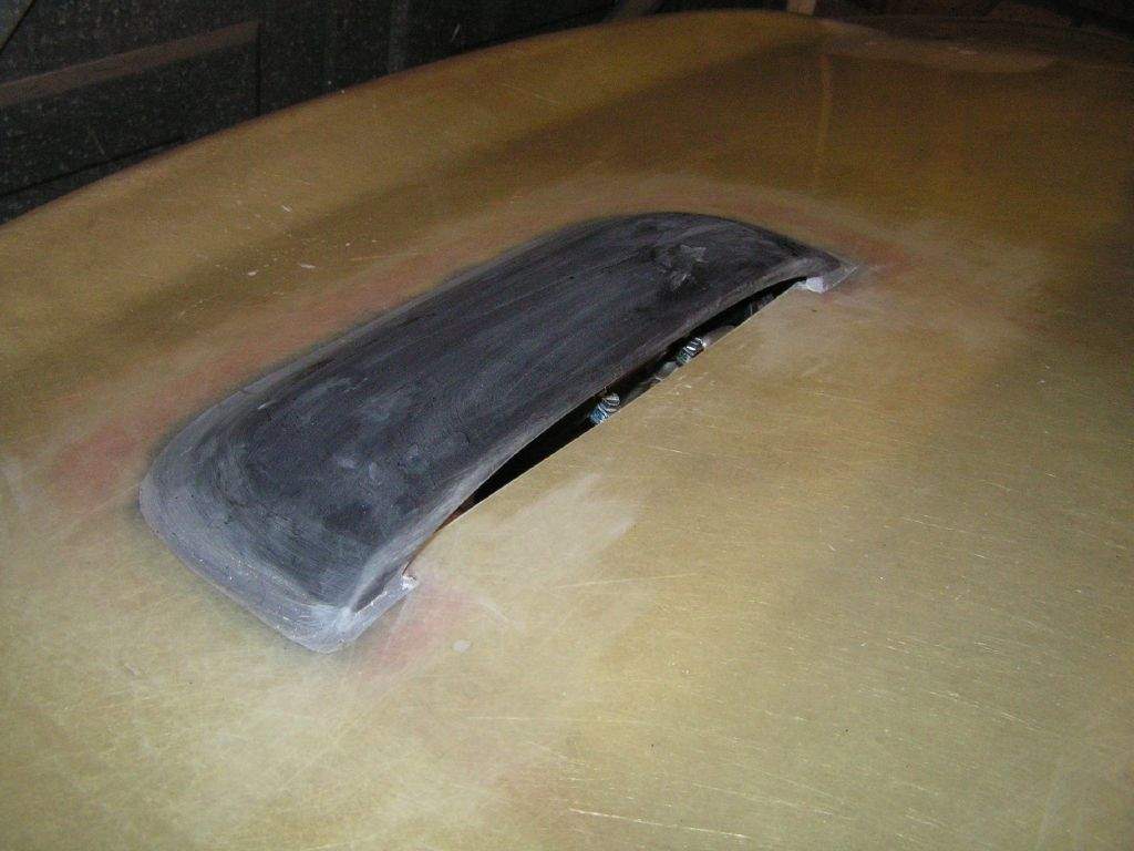
So, I marked out where I needed to remove more material around the existing hole in the engine cover, and then out came the dremel again. Here is the result, currently held in place with duct tape...
Went back to the cycle wings, yesterday's mistake wasn't as far wrong as I'd first thought, with about a half inch of material removed that shouldn't have been. I think I'll fibreglass in a small section when I fix the bighead fasteners to the underside of the wings, it won't take long. Checked that I could use the right hand cycle wing as a template for the left side, and yes, the stays seem pretty symmetrical. Cut out the second wing, and then messed around getting both wings to sit correctly.
17th June: 2h00m: Fibreglassed the scoop to the engine cover, with my other eye on the England vs Switzerland match... Once the fibreglass had hardened, after a couple of hours, I went around the join with car body filler. This will need a good sand to smooth the join. Had spoken to Jeremy Philips at Sylva earlier in the day about the wing mirrors. I had noticed that JP had built up some little platforms to lift the mirrors a bit higher. It turns out that this was mainly for cosmetic reasons, to ensure the mirror glass sat horizontally, but my mirrors can swivel in all directions and hence I could fit the mirror stalks straight to the body with no platforms. However, I think lifting the mirrors slightly will help with visibility over the rear wings, so I am considering whether to mould in some platforms using body filler, or whether to make up some wedge shaped spacers... As a quick test, I tried making a spacer out of some spare MDF that was lying around, I think this might work. MDF sounds a bit 'kit car', if you know what I mean, but it's easy to work with and if painted it should look fine, and they can at least be re-made out of a different material in the future if I have problems. 18th June: 2h00m: Attacked the body filler around the air scoop with wet & dry paper, with this being the end result:
Then Liz and I departed on our Summer holidays, so no updates will appear for the next two weeks! I'll be back on the Mojo in July... Summer has arrived too soon! Total time spent during June: 35h45m
|
||||||||||||||||||||||||||||||||||||||||||||||||
|
|
||||||||||||||||||||||||||||||||||||||||||||||||||